
Building an Autonomous Differential Robot
- Ahmed Gamal

- 4 days ago
- 3 min read
Creating an autonomous differential robot combines mechanical design, electronics, and software control to achieve independent navigation. This project highlights how to build a robot car that moves and makes decisions on its own using the Robot Operating System (ROS). The process involves selecting the right hardware, assembling components, and programming control algorithms to navigate environments without human input.

Understanding the Differential Robot Design
A differential robot uses two independently driven wheels on either side to steer and move. By varying the speed and direction of each wheel, the robot can turn, move forward, or reverse. This design is simple yet effective for indoor and outdoor navigation tasks.
Key features of the differential drive system include:
Two motorized wheels on a shared axis
A caster wheel or skid for balance
Compact chassis for mounting sensors and electronics
This setup allows precise control over movement and is well-suited for autonomous navigation when combined with sensors and control software.


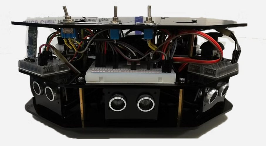
Essential Electronics and Hardware Components
Building an autonomous differential robot requires careful selection of hardware to ensure smooth operation and reliable control. The main components include:
Motors: Two DC motors with encoders provide feedback on wheel rotation, essential for accurate movement control.
Motor Drivers: H-bridge motor drivers control the direction and speed of the motors based on commands from the microcontroller.
Microcontroller or Single Board Computer: Devices like Raspberry Pi or NVIDIA Jetson run ROS and handle sensor data processing and control algorithms.
Sensors:
- LIDAR or ultrasonic sensors for obstacle detection and environment mapping
- IMU (Inertial Measurement Unit) for orientation and movement tracking
- Wheel encoders for odometry data
Power Supply: A rechargeable battery pack sized to provide sufficient voltage and current for motors and electronics.
Chassis: A sturdy frame to mount all components securely.
Choosing components that balance cost, performance, and compatibility with ROS is critical for project success.
Steps to Build the Autonomous Robot
Assemble the Chassis
Mount the motors, wheels, and caster wheel on the chassis. Ensure the frame is stable and components are securely fixed.
Install Electronics
Connect the motors to the motor drivers, then link the drivers to the microcontroller. Attach sensors in positions that maximize their field of view and data accuracy.
Set Up Power System
Connect the battery pack with proper voltage regulation and safety features. Verify all components receive the correct power levels.
Configure ROS Environment
Install ROS on the microcontroller or SBC. Set up packages for motor control, sensor data processing, and navigation.
Develop Control Algorithms
Program differential drive control using encoder feedback. Implement sensor fusion to combine LIDAR, IMU, and odometry data for accurate localization.
Test Autonomous Navigation
Run simulations and real-world tests to tune parameters. Adjust speed, turning radius, and obstacle avoidance behaviors.
Iterate and Improve
Analyze performance data and refine software and hardware as needed to enhance reliability and efficiency.
Implementing Control with ROS
ROS provides a flexible framework to manage the robot’s sensors, actuators, and navigation stack. Key ROS components for this project include:
ros_control for motor command interfaces
robot_localization to fuse sensor data for position estimation
move_base for path planning and obstacle avoidance
By integrating these packages, the robot can autonomously plan routes, detect obstacles, and adjust its path in real time. ROS also supports visualization tools like RViz to monitor the robot’s status during development.


Comments